Table Of Contents

Best Practices for Segmental Retaining Wall Design
The intent of this document is to communicate the best practices for design of Segmental Retaining Walls (SRW) as determined by Allan Block Corporation based on 30 plus years of research, design and field experience.
Navigate by using the arrows at the top, or jump directly to specific sections with the Table of Contents
   
Part 2 - Best Practice Considerations

Chapter 1.0 Design Guidelines and Pre-Construction Considerations
  • 1.1 Meeting with Owner
  • 1.2 Determining when Engineering is Required
  • 1.3 Existing and Proposed Utilities
  • 1.4 Wall Layout, height and geometry
  • 1.5 Geotechnical Report Considerations
  • 1.6 Understanding sites soils
  • 1.7 Site Visit
  • 1.8 Temporary Load Considerations
  • 1.9 Scope of Responsibility and Design Methodologies
  • 1.10 Minimum Design Safety Factors
  • 1.11 Coherent Gravity Mass and Connection Strength Considerations
  • 1.12 Contractor Requirements
  • 1.13 Manufactured Product Specifications
  • 1.14 Freeze Thaw Durability
  • 1.15 Pre-Construction Meeting
  • 1.16 Visiting the Site During Construction
  • 1.17 Construction Drawings
  • 1.18 For the Bidding Process
  • 1.19 Quality Control, Quality Assurance
   

Chapter 2.0 Typical Wall Construction
  • 2.1 Inspection of Materials
  • 2.2 Allowable Foundation Soils
  • 2.3 Allowable Infill Soils
  • 2.4 Wall Rock Guidelines
  • 2.5 Soil Parameter Verification
  • 2.6 Typical Wall Embedment
  • 2.7 Base Trench Requirements
  • 2.8 Base Trench Considerations
  • 2.9 Minimum Grid Lengths
  • 2.10 Initial Grid Location
  • 2.11 Maximum Grid Spacing
  • 2.12 Minimum Wall Facing Depth
  • 2.13 Capping the Wall
   

Chapter 3.0 Water Management - Typical
  • 3.1 Identifying Potential Water Sources
  • 3.2 Blanket and Chimney Drains
  • 3.3 Venting of Drain Pipes
  • 3.4 Above Grade Water Management
   

Chapter 4.0 Water Management - Alternate Drain
  • 4.1 Alternate Drain Locations
  • 4.2 Heel Drain Recommendations
   

Chapter 5.0 Water Application
  • 5.1 Below Grade Water Management
  • 5.2 Water Application Construction
   

Chapter 6.0 Soil and Compaction
  • 6.1 Understanding sites soils
  • 6.2 Allowable Foundation Soils
  • 6.3 Allowable Infill Soils
  • 6.4 Wall Rock Guidelines
  • 6.5 Soil Parameter Verification
  • 6.6 Inspection and Testing Recommendations
  • 6.7 Compaction Requirements at the Face of Wall
  • 6.8 Maximum Compaction Lift Spacing
  • 6.9 Compaction Requirements for Backfill Soil
  • 6.10 Testing Location and Frequencies
  • 6.11 Water Management During Construction
  • 6.12 Wall Step Ups in Base Course
  • 6.13 Stair Considerations
   

Chapter 7.0 Geogrid Reinforcement Requirements, Corner and Radius Design Practices
  • 7.1 Geogrid Reinforcement Requirements and Certification
  • 7.2 Proper Grid Orientation
  • 7.3 Wall Rock Design for Corners and Curved Walls
   

Chapter 8.0 Tall Walls Considerations
  • 8.1 Tall Wall Definition
  • 8.2 Variable Rock Thickness at Face
  • 8.3 Compaction and Soil Considerations
  • 8.4 Increased Forces in Lower Portion of Walls
  • 8.5 Global Stability of Tall Walls
  • 8.6 Internal Compound Stability Calculations
  • 8.7 Minimum Wall Facing Depth
   

Chapter 9.0 Global Stability - General
  • 9.1 Wall Embedment with Toe Slope
  • 9.2 When to Analyze for Global Stability
  • 9.3 Increasing Global Stability Options
  • 9.4 Effect of Groundwater on Global Stability
   

Chapter 10.0 Global Stability - Terraced
  • 10.1 Terraced Wall Considerations
  • 10.2 Upper Wall Influence - Surcharge
  • 10.3 Height and Grading
  • 10.4 Grid Considerations
  • 10.5 Compaction and Testing
  • 10.6 Toe and Heel Drain
  • 10.7 Global Stability
  • 10.8 Tall Wall Terraces
   

Chapter 11.0 Seismic Considerations
  • 11.1 Recommendations Associated with Seismic Loading
  • 11.2 Slope Above Seismically Loaded Walls
  • 11.3 Mononobe-Okabe Slope Above Limitations
  • 11.4 Alternate Design Approach – Trial Wedge Method
   

Chapter 12.0 Above Wall Considerations
  • 12.1 Minimum Grid Lengths at the Top of the Wall
  • 12.2 Fences and Railings
  • 12.3 Slopes Above the Wall
  • 12.4 Stability of Slopes Above
  • 12.5 Compaction Requirements for Slopes Above
  • 12.6 Reinforcing Slopes Above Walls
  • 12.7 Plantings
   

Allan Block Resources
Allan Block Spec Book
AB Engineering Manual
AB Commercial Manual
Seismic Testing Book
   
Search
 

Chapter 3: Water Management - Typical

Click on the topics below to view more information on the best practices for Allan Block segmental retaining wall design for residental and commercial applications.


3.1    Identify localized water sources such as storm drains and drop structures. Consult with Project Site Civil Engineer to ensure that water will not be introduced into the reinforced mass. Consider excess irrigation or natural groundwater sources.

  1. Utilize Water Management Section 3 in the Allan Block Spec Book.
    1. Surface drainage
      1. Must drain away from the top and bottom of the wall.
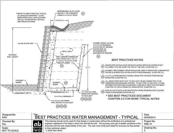
      2. Slopes above walls should have swales placed above so water is not allowed to flow over the top of the wall.
      3. During construction, Surface water must not be allowed to pond or be trapped in the area above the wall or at the toe of the wall. Surface water must be directed away from partially constructed walls at the end of each day’s construction.
      4. Provisions, such as check valves, to prevent flooding from broken lines or heads must be put in place to stop over irrigation above walls.
  2. Additional wall rock should be added around all storm drains and drop structures to aid in draining any areas of the pipe that may leak.
  3. If there are any utilities within the reinforcement zone, place gravel around them to generate good compaction levels.
Project site plan for proposed retaining wall

Figure 3-1: Surface Water Management


3.2   Use a combination of blanket and chimney drains

  1. If site soils are used that do not have granular characteristics, a chimney and blanket drain should be considered to ensure the infill mass stays as dry as possible. Unless otherwise directed by the geotechnical engineer, a blanket and chimney drain should be used when infill soils have a less than 30 degree friction angle when determined without the use of cohesion.
  2. If migrating subsurface water is on the site a chimney and blanket drain should be used.
  3. See Allan Block Chimney and Blanket Drain detail above.
  4. Drain material to be consistent with wall rock material. For more information on wall rock material see Chapter 2 Typical Wall Construction.
  5. Manufactured chimney and blanket drains to be approved by the geotechnical and/or the local engineer of record prior to use.

3.3    Location, type, and venting of drain pipes.

  1. Utilize Water Management Sections 1.4 and 1.5 in the Allan Block Spec Book.
  2. 4 in (10 cm) perforated flexible drain pipe or rigid perforated pipes are recommended.
  3. When a rigid perforated pipe is used, it should be placed with holes down.
  4. All drain pipes must exit to daylight or be connected to an underground drainage system. Use Allan Block Alternate Drain detail for examples of venting to daylight.
    1. It is recommended that a minimum 1% gradient be maintained on the placement of the pipe with outlets on 50 ft (15 m) centers, or 100 ft (30 m) centers if the pipe is crowned between the outlets.
    2. It is recommended that all pipe outlets be configured to be protected from crushing or plugging from other means.
  5. For terraced applications, the toe and heel drains shall be routed as to not exit on the lower terraces. Drainpipes shall be extended to provide a path for water to be channeled away from the wall structure. Pipes at exit locations shall be marked to facilitate identification of where water is draining from.
  6. Drain pipes exiting to daylight through the wall should be installed with rodent screen to prevent nesting within the pipe. Cut adjoining block to allow for installation of a manufactured drain cover. Alternatively, Wall Drain Pro could be used without the requirement of cutting block. See more information here on Wall Drain Pro.

3.4    Above grade water management plan and finishing of the compacted soil mass.

  1. Surface water that cannot be diverted from the wall must be collected with surface drainage swales and drained laterally in order to disperse the water around the wall structure. Construction of a typical swale system shall be in accordance with Water Management - Typical Drawing No. 2.0 above. Also see Chapter 12 for further discussion on above wall considerations.