Table Of Contents

Best Practices for Segmental Retaining Wall Design
The intent of this document is to communicate the best practices for design of Segmental Retaining Walls (SRW) as determined by Allan Block Corporation based on 30 plus years of research, design and field experience.
Navigate by using the arrows at the top, or jump directly to specific sections with the Table of Contents
   
Part 2 - Best Practice Considerations

Chapter 1.0 Design Guidelines and Pre-Construction Considerations
  • 1.1 Meeting with Owner
  • 1.2 Determining when Engineering is Required
  • 1.3 Existing and Proposed Utilities
  • 1.4 Wall Layout, height and geometry
  • 1.5 Geotechnical Report Considerations
  • 1.6 Understanding sites soils
  • 1.7 Site Visit
  • 1.8 Temporary Load Considerations
  • 1.9 Scope of Responsibility and Design Methodologies
  • 1.10 Minimum Design Safety Factors
  • 1.11 Coherent Gravity Mass and Connection Strength Considerations
  • 1.12 Contractor Requirements
  • 1.13 Manufactured Product Specifications
  • 1.14 Freeze Thaw Durability
  • 1.15 Pre-Construction Meeting
  • 1.16 Visiting the Site During Construction
  • 1.17 Construction Drawings
  • 1.18 For the Bidding Process
  • 1.19 Quality Control, Quality Assurance
   

Chapter 2.0 Typical Wall Construction
  • 2.1 Inspection of Materials
  • 2.2 Allowable Foundation Soils
  • 2.3 Allowable Infill Soils
  • 2.4 Wall Rock Guidelines
  • 2.5 Soil Parameter Verification
  • 2.6 Typical Wall Embedment
  • 2.7 Base Trench Requirements
  • 2.8 Base Trench Considerations
  • 2.9 Minimum Grid Lengths
  • 2.10 Initial Grid Location
  • 2.11 Maximum Grid Spacing
  • 2.12 Minimum Wall Facing Depth
  • 2.13 Capping the Wall
   

Chapter 3.0 Water Management - Typical
  • 3.1 Identifying Potential Water Sources
  • 3.2 Blanket and Chimney Drains
  • 3.3 Venting of Drain Pipes
  • 3.4 Above Grade Water Management
   

Chapter 4.0 Water Management - Alternate Drain
  • 4.1 Alternate Drain Locations
  • 4.2 Heel Drain Recommendations
   

Chapter 5.0 Water Application
  • 5.1 Below Grade Water Management
  • 5.2 Water Application Construction
   

Chapter 6.0 Soil and Compaction
  • 6.1 Understanding sites soils
  • 6.2 Allowable Foundation Soils
  • 6.3 Allowable Infill Soils
  • 6.4 Wall Rock Guidelines
  • 6.5 Soil Parameter Verification
  • 6.6 Inspection and Testing Recommendations
  • 6.7 Compaction Requirements at the Face of Wall
  • 6.8 Maximum Compaction Lift Spacing
  • 6.9 Compaction Requirements for Backfill Soil
  • 6.10 Testing Location and Frequencies
  • 6.11 Water Management During Construction
  • 6.12 Wall Step Ups in Base Course
  • 6.13 Stair Considerations
   

Chapter 7.0 Geogrid Reinforcement Requirements, Corner and Radius Design Practices
  • 7.1 Geogrid Reinforcement Requirements and Certification
  • 7.2 Proper Grid Orientation
  • 7.3 Wall Rock Design for Corners and Curved Walls
   

Chapter 8.0 Tall Walls Considerations
  • 8.1 Tall Wall Definition
  • 8.2 Variable Rock Thickness at Face
  • 8.3 Compaction and Soil Considerations
  • 8.4 Increased Forces in Lower Portion of Walls
  • 8.5 Global Stability of Tall Walls
  • 8.6 Internal Compound Stability Calculations
  • 8.7 Minimum Wall Facing Depth
   

Chapter 9.0 Global Stability - General
  • 9.1 Wall Embedment with Toe Slope
  • 9.2 When to Analyze for Global Stability
  • 9.3 Increasing Global Stability Options
  • 9.4 Effect of Groundwater on Global Stability
   

Chapter 10.0 Global Stability - Terraced
  • 10.1 Terraced Wall Considerations
  • 10.2 Upper Wall Influence - Surcharge
  • 10.3 Height and Grading
  • 10.4 Grid Considerations
  • 10.5 Compaction and Testing
  • 10.6 Toe and Heel Drain
  • 10.7 Global Stability
  • 10.8 Tall Wall Terraces
   

Chapter 11.0 Seismic Considerations
  • 11.1 Recommendations Associated with Seismic Loading
  • 11.2 Slope Above Seismically Loaded Walls
  • 11.3 Mononobe-Okabe Slope Above Limitations
  • 11.4 Alternate Design Approach – Trial Wedge Method
   

Chapter 12.0 Above Wall Considerations
  • 12.1 Minimum Grid Lengths at the Top of the Wall
  • 12.2 Fences and Railings
  • 12.3 Slopes Above the Wall
  • 12.4 Stability of Slopes Above
  • 12.5 Compaction Requirements for Slopes Above
  • 12.6 Reinforcing Slopes Above Walls
  • 12.7 Plantings
   

Allan Block Resources
Allan Block Spec Book
AB Engineering Manual
AB Commercial Manual
Seismic Testing Book
   
Search
 

Chapter 7: Geogrid Reinforcement Requirements, Corner and Radius Design Practices

Click on the topics below to view more information on the best practices for Allan Block segmental retaining wall design for residental and commercial applications.


7.1   Certification to ensure proper materials for the geogrid reinforcement. Most geogrids used for soil reinforcement are manufactured from polyester fiber. To ensure a high quality product, use a geosynthetic reinforcement that has obtained an NTPEP Report.

  1. There are many different international manufacturers that are supplying geogrid reinforcement, and they are not all equal. It is important to understand what influences the durability of the geogrid. The U.S. Federal Highway Administration identified three key factors:
    1. Soils that have a pH of 10 or more represent an environment that could potentially degrade the geogrid faster especially in the presence of sufficient water.
    2. Polyester molecular weight – the size of the polymer molecule has a significant influence on the chemical durability.
    3. Polyester carboxyl end group (CEG) – grids are less susceptible to degradation when they have fewer CEG in their molecular structure.
  2. Establish minimum requirements when using polyester geogrids. CMHA adopted the guidelines that the FHWA set for geogrid reinforcement. All polyester geogrids submitted for approval must be made of polyester fiber that meets the following specifications:
    1. Molecular weight greater than 25,000 g/mol
    2. Caboxyl End Group less than 30 mmol/Kg
  3. The certification, obtained from the geogrid manufacturer, must originate from the actual manufacturer of the fiber to show conformance with the specification.
  4. Designer must consider soils that have a pH of 10 or more represent an environment that could potentially degrade the geogrid faster especially in the presence of sufficient water and may require additional design criteria.

7.2   Proper orientation of grid and placement.

  1. Typical commercial geogrid is uniaxial and strong in the roll direction and should be placed in sheets perpendicular to the wall facing.
  2. Utilize Section 2 – Part 3.3 Geogrid Installation in the Allan Block Spec Book.
    1. Cut geogrid to designed embedment length and place on top of the Allan Block units to the back edge of the raised front lip or within 1 in (2.5 cm) of the retaining wall face when using AB Fieldstone.
    2. Extend away from wall approximately 3% above horizontal on compacted infill soils.
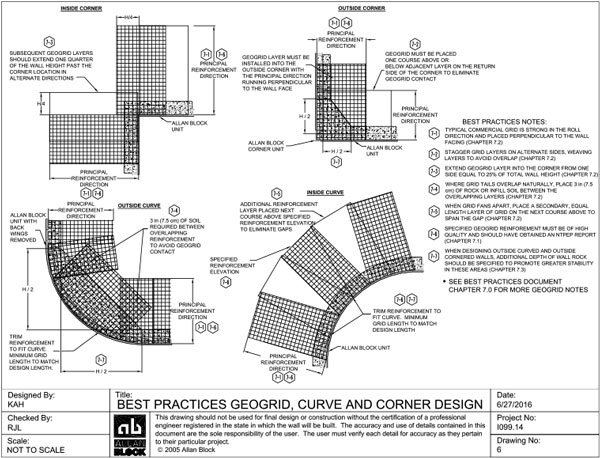
  3. For straight walls, placement of adjacent sheets of geogrid should be side-by-side without any overlap. For walls with corners or curves the following are the best practice method of placement:
    1. For outside corners, to avoid overlapping grid layers, grids should be stagger by one course on either side of the corner, weaving the strong direction from bottom to top of wall. See Allan Block standard detail 10 in Allan Block Spec Book.
    2. For inside corners, extend the geogrid layer into the corner from one side a distance equal to 25% of the total wall height. Alternate extended geogrid layer from side to side per course to create a geogrid weave as wall is built. See Allan Block standard detail 9 in Allan Block Spec Book.
    3. For outside curves, where grid tails overlap naturally, place roughly 3 in (7.5 cm) of wall rock or infill soil between the overlapping layers. See Allan Block standard detail 12 in Allan Block Spec Book.
    4. For inside curves, where grid layers fan apart, place a secondary, equal length, layer of grid on the next course above the fanned gap. See Allan Block standard detail 11 in Allan Block Spec Book.
Grid Location

Figure 7-1: Grid Location


7.3   Wall rock design for corners and curved walls.

  1. When designing curved and radius wall segments the designer should provide details to the installer for wall rock placement.
    1. For inside curved and inside cornered walls, the minimum wall rock specified should follow Section 6.4 (paragraph a) and Section 8.2 for Tall Wall applications.
    2. For outside curved and outside cornered walls, additional depth of wall rock should be specified to promote greater stability in these areas. Additional depth of wall rock is dependent on the total height of the wall and should be a minimum of H/2 as detailed in Drawing No. 6 on the top of this page.